


Welcome To kVA Process Transformers
Manufacturer Of Robust Furnace Transformers
We Customize Furnace Transformers for Industries
| 25+ YEARS OF EXPERIENCE
Welcome To kVA Process Transformers
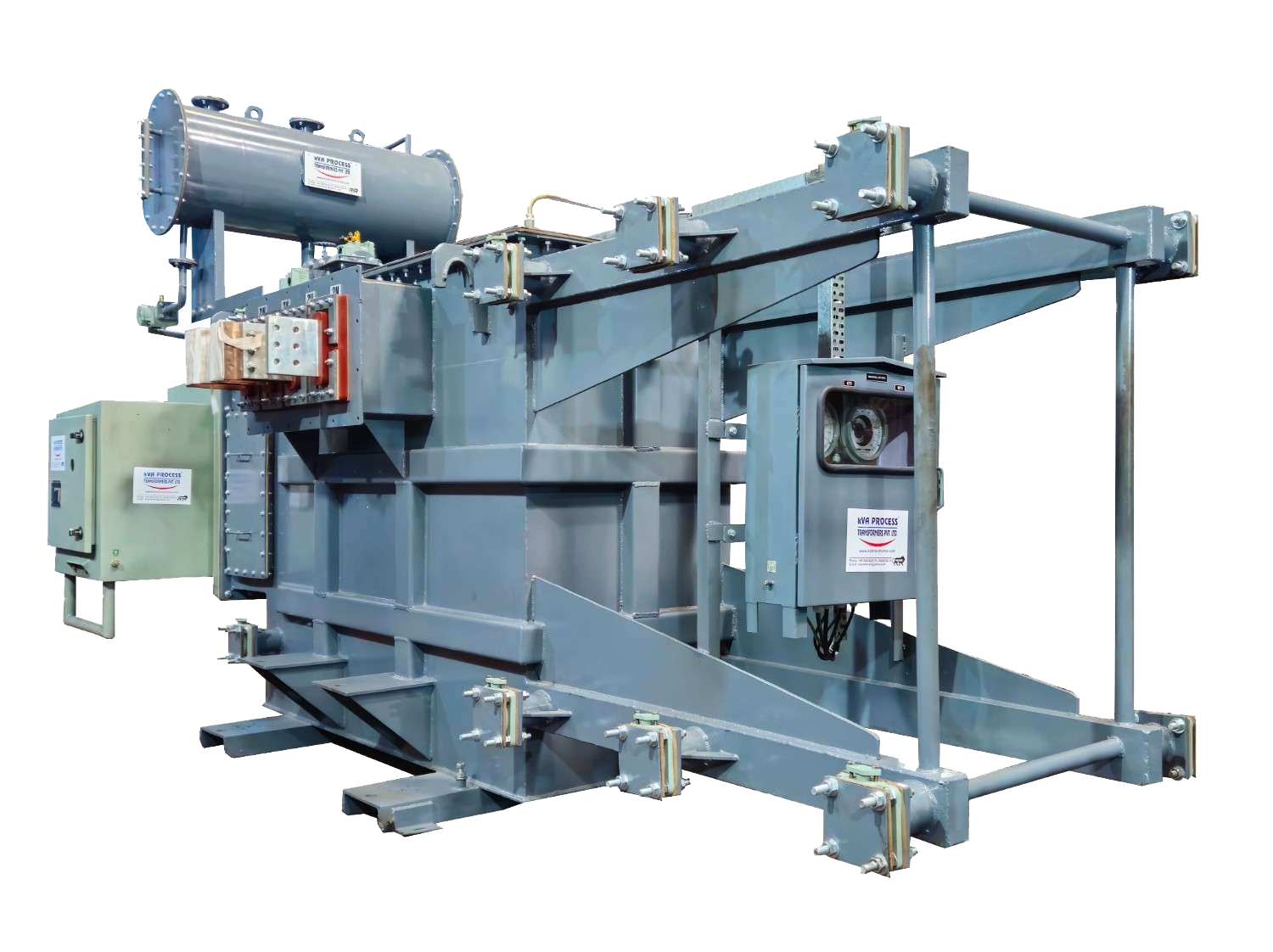
We, KVA Process Transformers Pvt. Ltd., are established manufacturers of a wide range of transformers and electrical equipment, including Submerged Arc Melting Duty Transformers, Electric Arc Furnace Transformers (with or without Series Reactors), Ladle Refining Furnace Duty Transformers, Induction Furnace Transformers, Converter & Rectifier Duty Transformers, Power & Distribution Transformers, and many more.

| OUR PRODUCTS
OUR RANGE OF PRODUCTS
We produce ISI Certified transformers, ensuring low losses & high efficiency. Manufactured with the best quality materials to utmost perfection, check out our standard range of transformers below. Feel free to contact us at kVA Process Transformers for more details about the same.
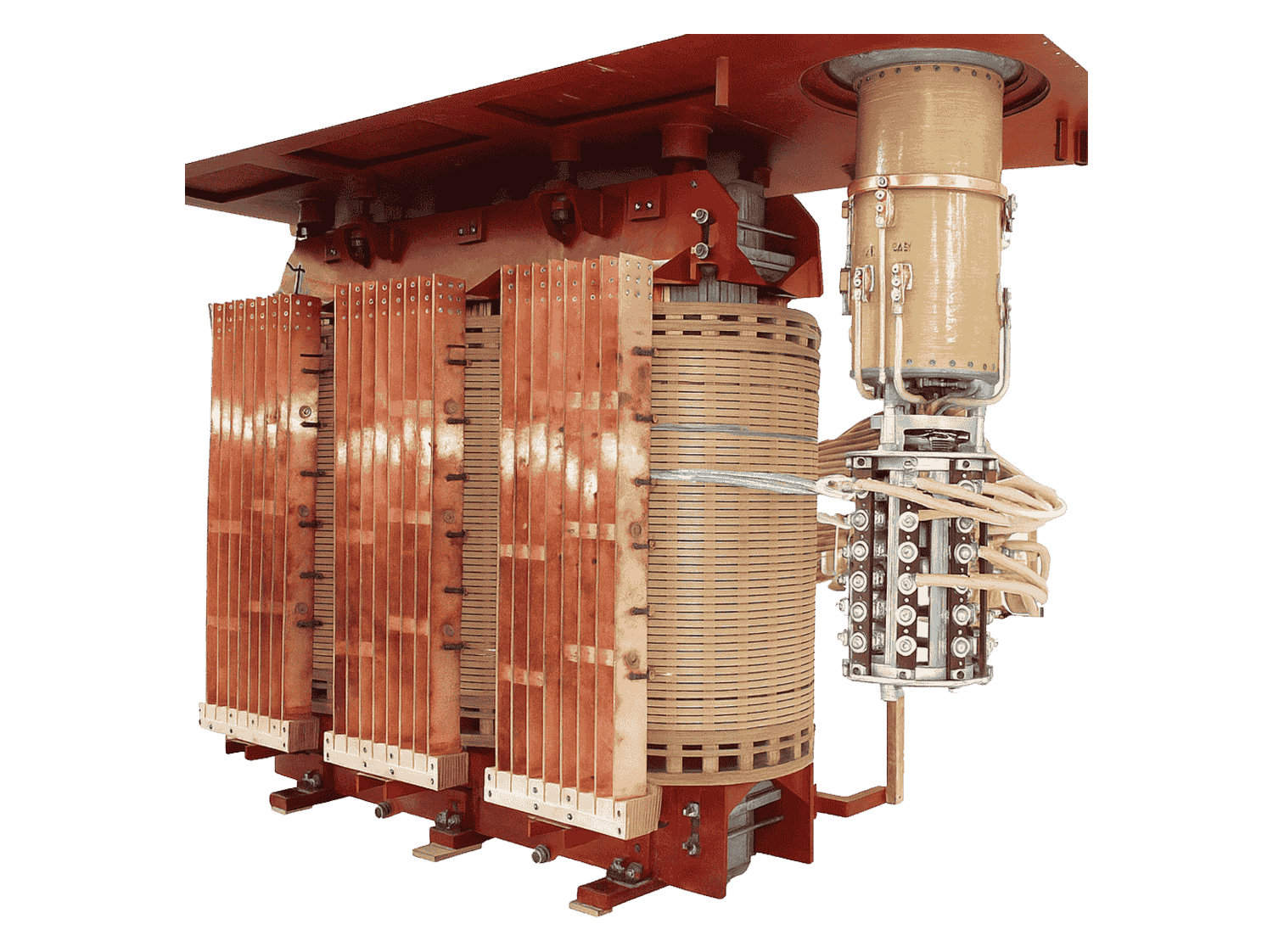
SUBMERGED ARC FURNACE TRANSFORMER
Know More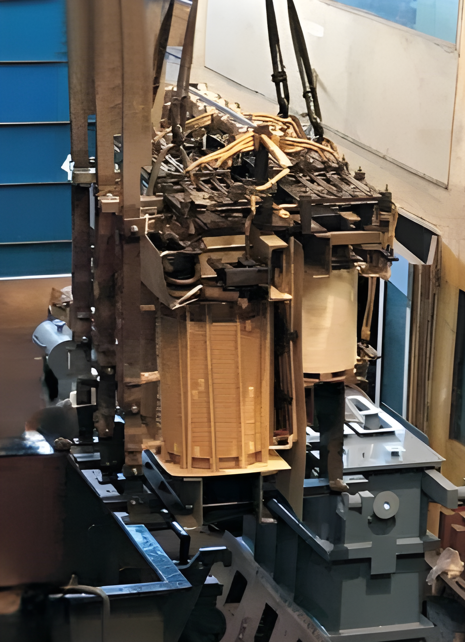
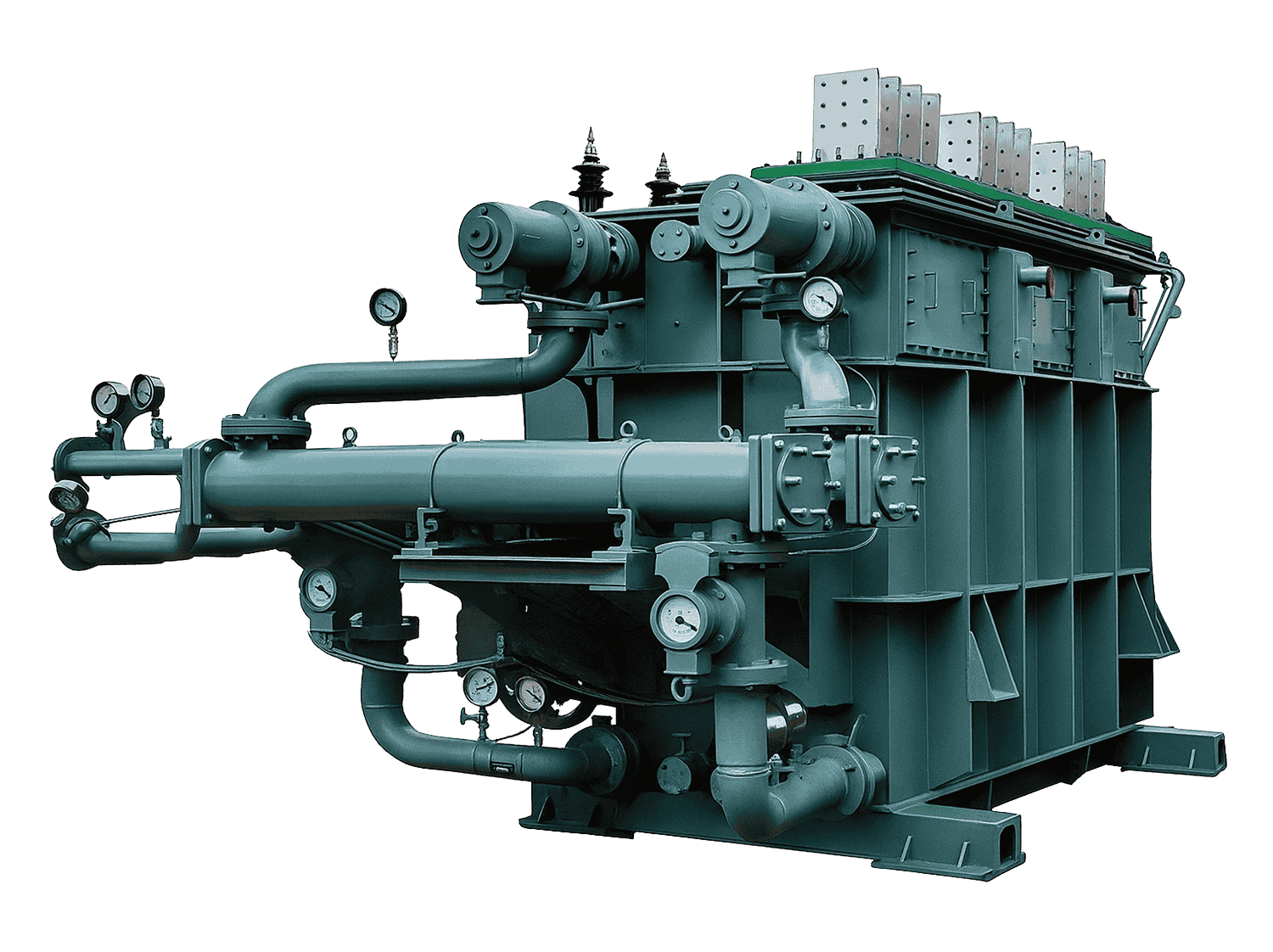
ELECTRIC ARC FURNACE TRANSFORMER
Know More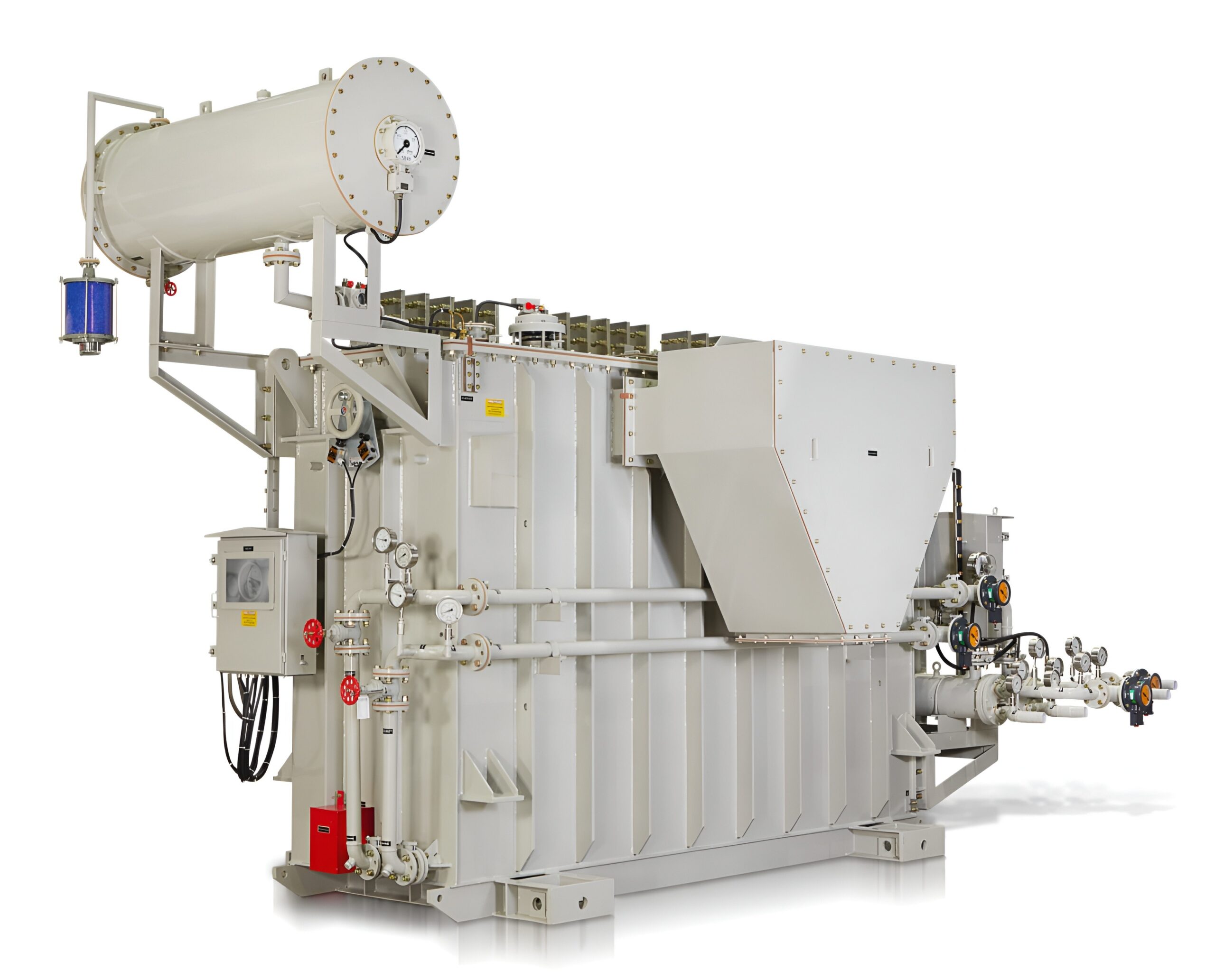
LADLE REFINING FURNACE TRANSFORMER
Know More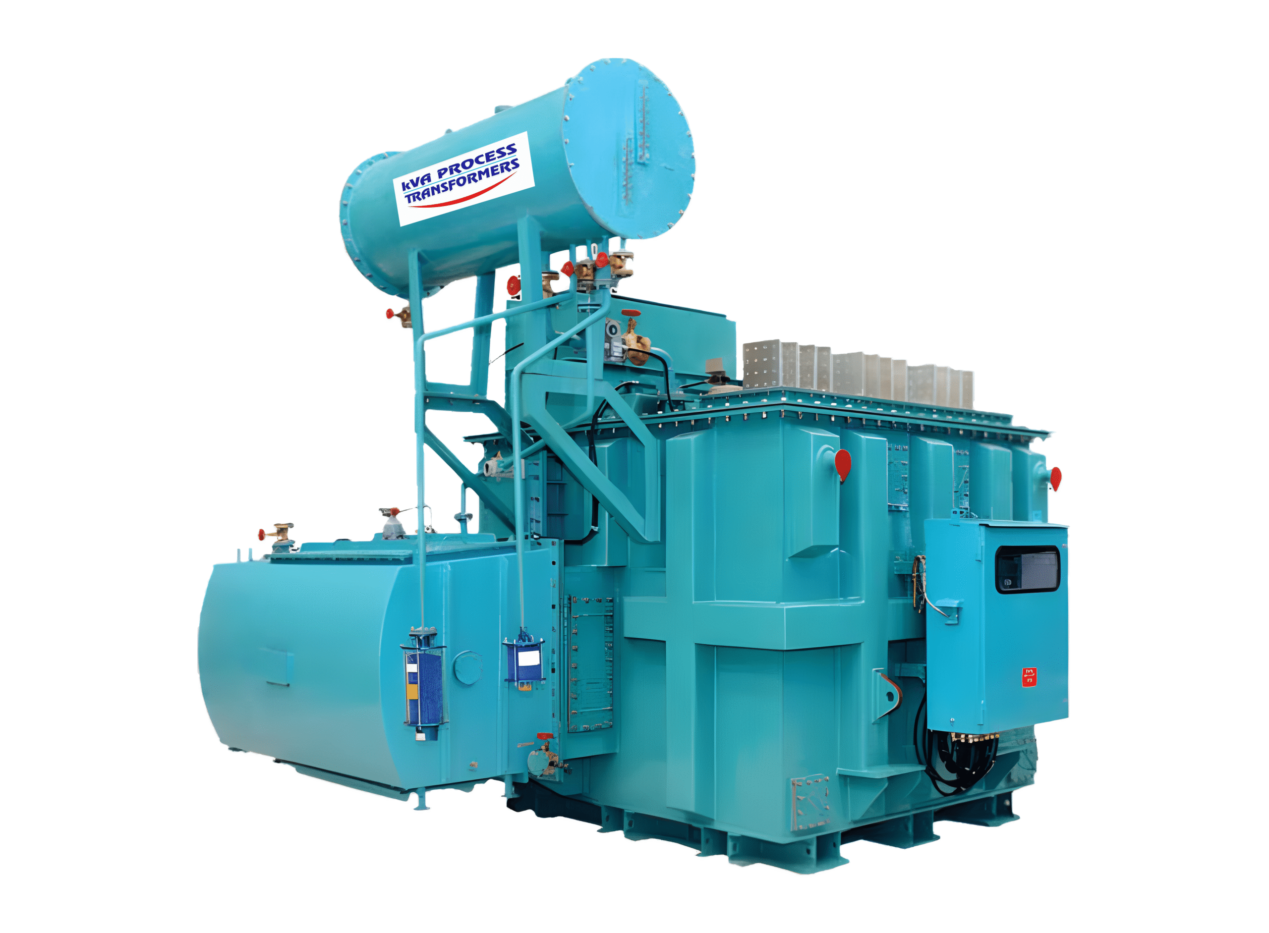
INDUCTION FURNACE TRANSFORMER
Know More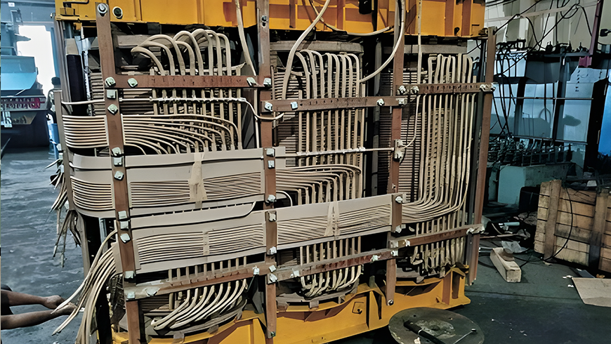
RECTIFIER /CONVERTER DUTY TRANSFORMER
Know More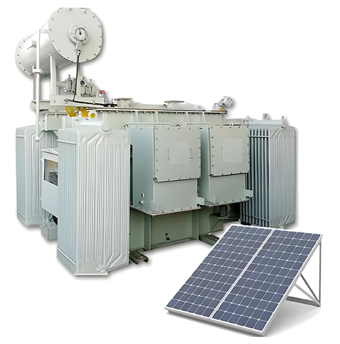
SOLAR TRANSFORMER
Know More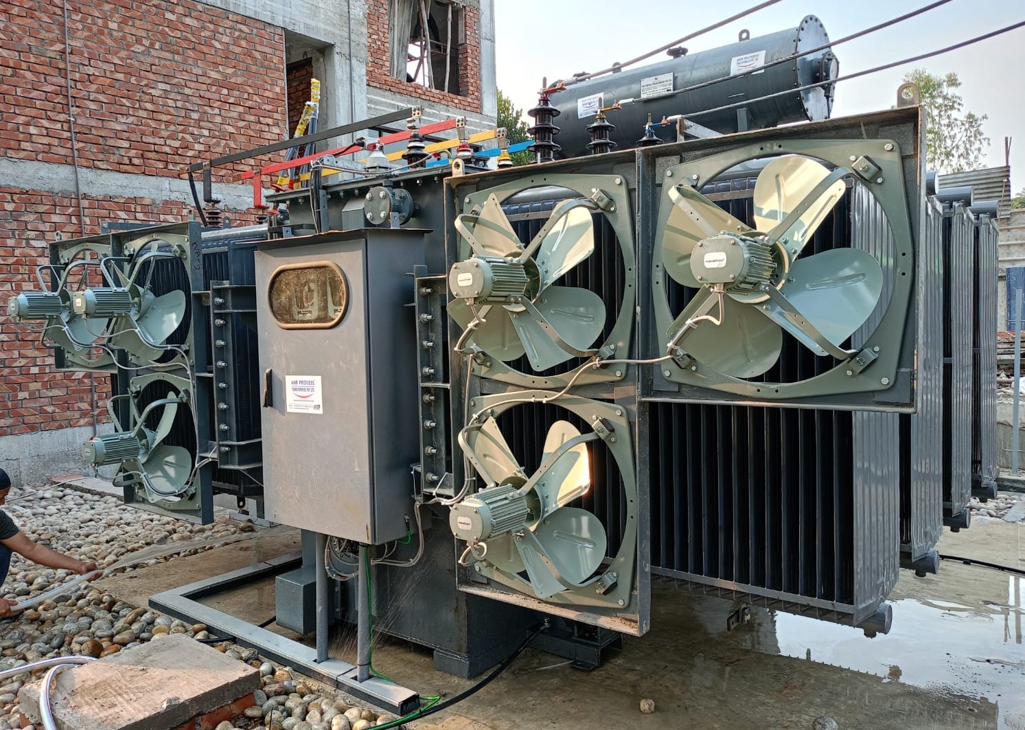
POWER TRANSFORMER
Know More
AUXILIARY TRANSFORMER
Know More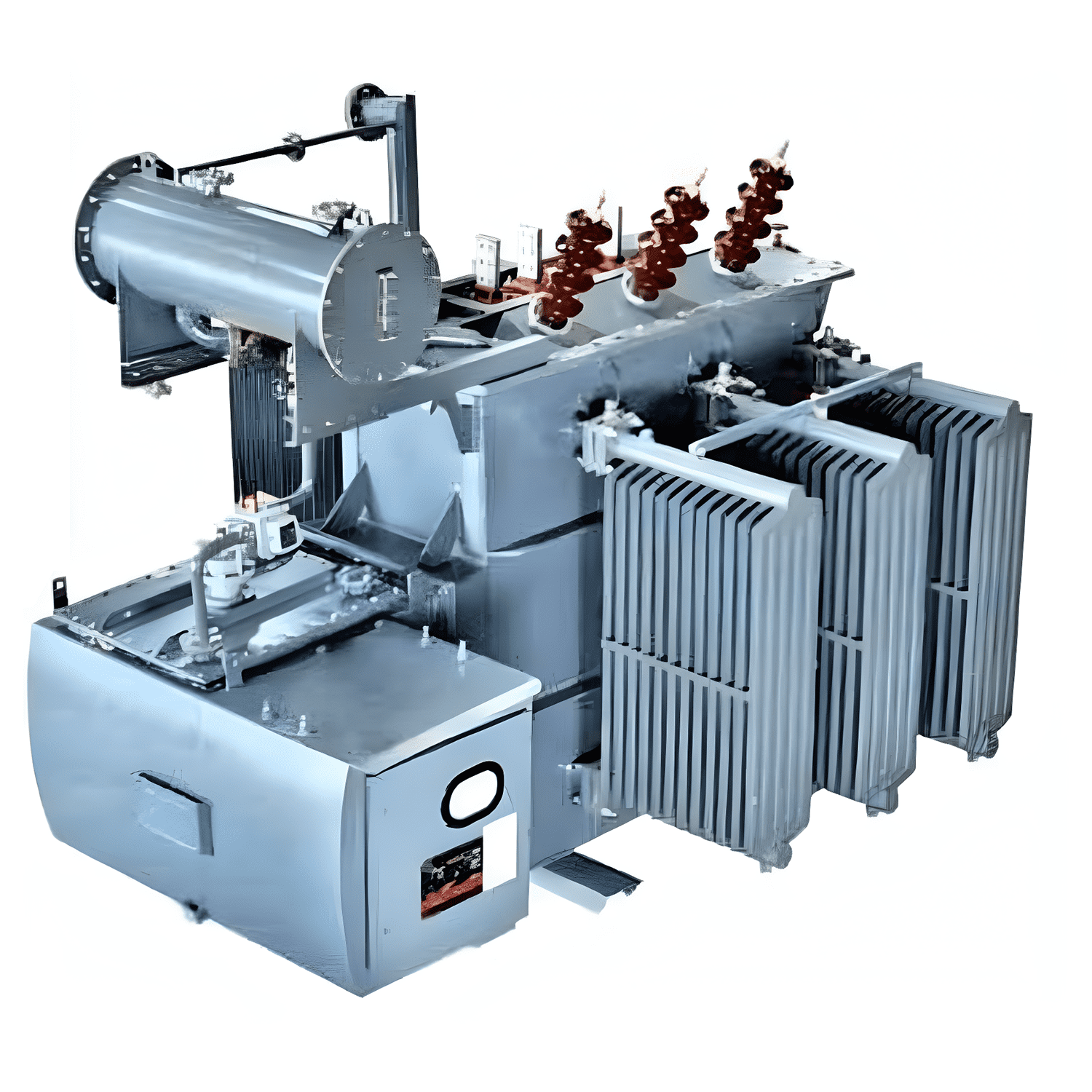
AUTOMATIC STEP VOLTAGE REGULATOR
Know More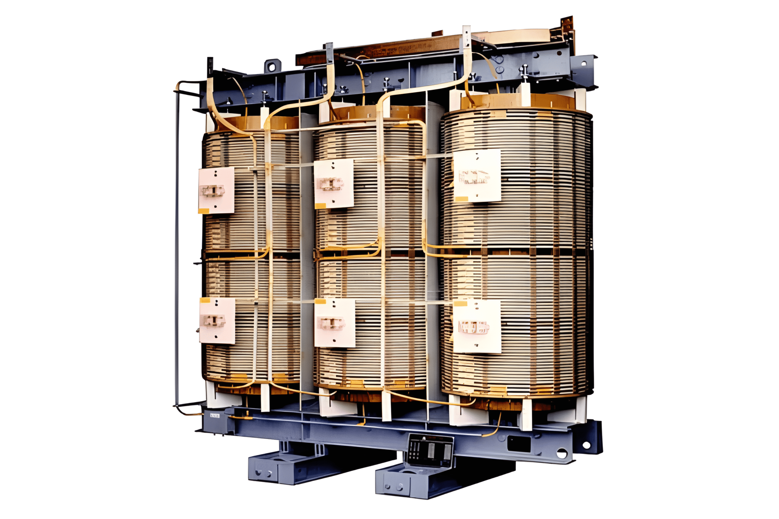
DRY TYPE TRANSFORMER
Know More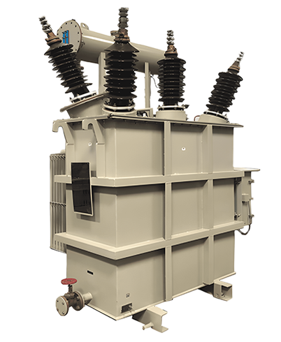
EARTHING TRANSFORMER
Know More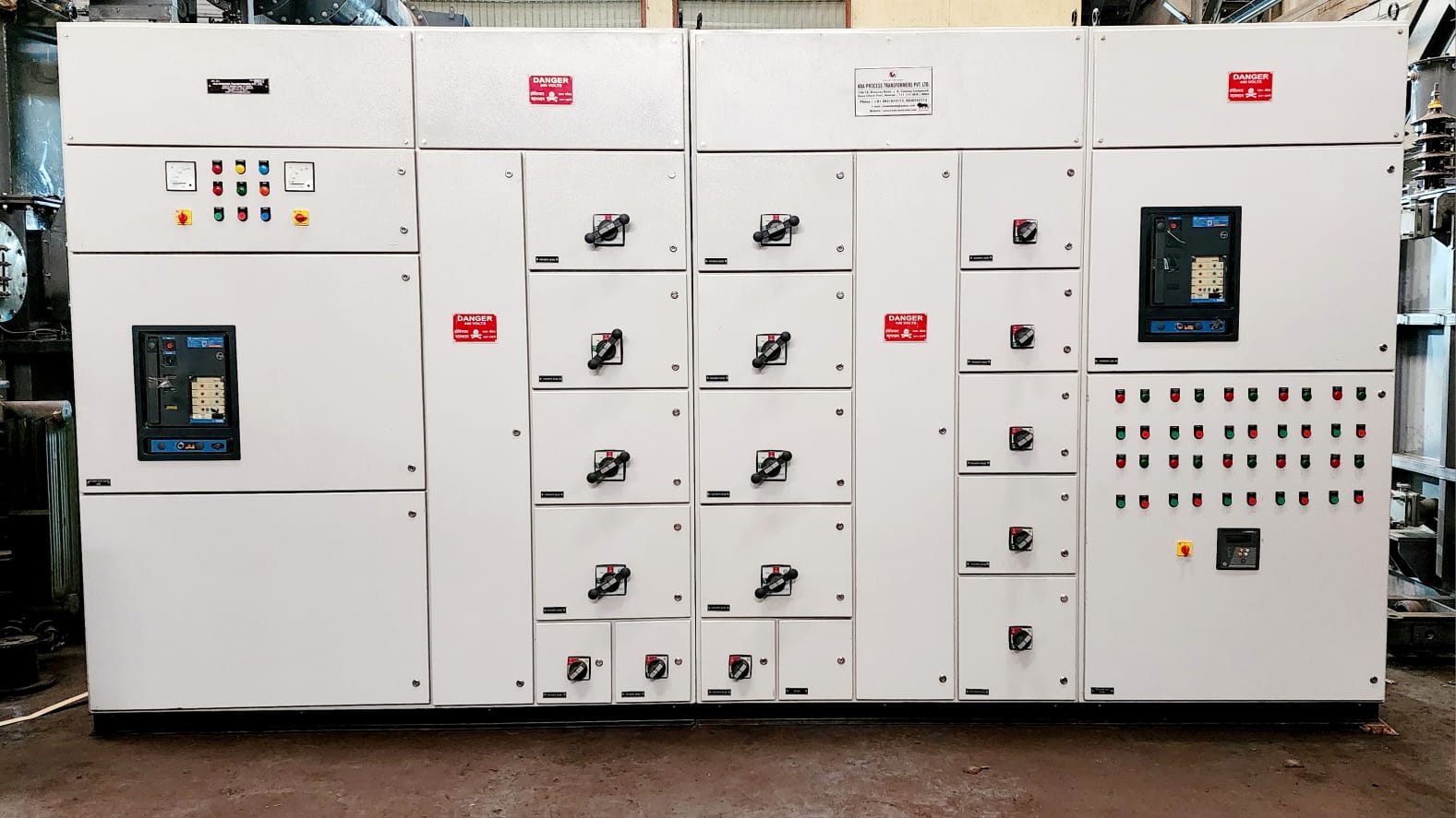
LT PANEL BOARD
Know More| WHY US ?
WHY CHOOSE US ?

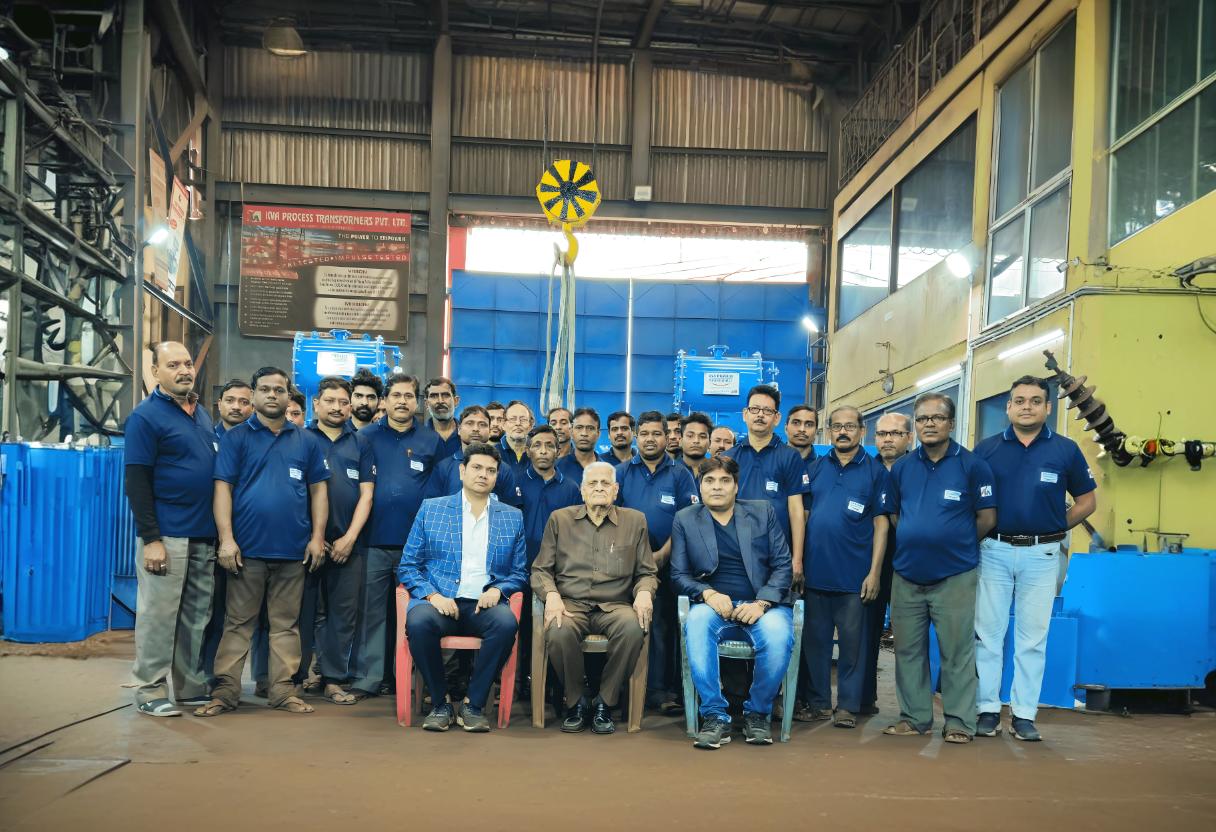
14800 sq. ft. state of the art manufacturing facility

Eco Friendly Operation and Manufacturing

Commitment to manufacturing quality products using internationally accepted norms

Fully equipped laboratory with high tech advanced instruments and highly qualified personnel

Best in class infrastructure

More than 25 years of product Knowledge
WE HAVE WELL EQUIPPED MANUFACTURING FACILITY WITH
25+ YEARS OF EXPERIENCE
Learn More About Our Process
| OUR PORTFOLIO
GALLERY
Frequently Asked Questions
As a leading transformer manufacturer in India, kVA Process Transformers specializes in a wide array of high-performance furnace transformers designed for the most demanding industrial environments. Our extensive product range is engineered for reliability and peak performance, including Submerged Arc Furnace Transformers, Electric Arc Furnace Transformers (with or without Series Reactors), Ladle Refining Furnace (LRF) Duty Transformers, and Induction Furnace Transformers, among others.
Yes, absolutely. At kVA Process Transformers, we understand that every industrial application has unique requirements. Our core strength lies in our ability to engineer and deliver fully customized transformers. Our expertise in these specialized products is a key reason we are considered among the best transformer manufacturers in Kolkata, providing robust and efficient solutions for the metallurgical and heavy engineering sectors.
Quality is the cornerstone of our manufacturing process. To ensure we consistently rank as the best transformer manufacturer in India, all our products are built in compliance with the highest national and international standards.
We ensure the safety and long-term reliability of our transformers through a meticulous, multi-stage process that combines advanced technology with deep industry expertise.
Our furnace transformers are engineered for exceptional durability and a long operational lifespan. While the exact service life depends on factors like operational intensity, environmental conditions, and adherence to maintenance schedules, our transformers are built to provide reliable service for many years. By using superior materials and adhering to the quality control standards, we deliver products that offers an outstanding return on investment, a hallmark of the best transformer manufacturer in Kolkata.
Yes, our commitment to our customers extends far beyond the sale. kVA Process Transformers offers comprehensive after-sales support and maintenance services. Our dedicated support team is readily available to provide expert technical assistance, address any operational queries, and offer prompt troubleshooting. We believe that timely and effective support is crucial for maintaining the peak efficiency and longevity of your transformers. We also proudly offer both transformer repairing and hiring.
Requesting a quote is simple and convenient. You can reach our team through any of the following channels: Phone: Call us directly at +91 98318 23173 or +91 98302 52113. Email: Send your specifications and inquiries to info@kvatransformer.com Online Form: Complete the "Send Message" form on our contact page. WhatsApp: Click the "WHATSAPP US" button for an instant connection.
The lead time for delivery varies based on the transformer's specifications, the complexity of customization, and current production schedules. As a premier transformer manufacturer in India, we are committed to optimizing our production process to ensure timely delivery without compromising our high-quality standards. Upon receiving your specific requirements, we will provide you with an accurate and reliable delivery timeline along with your formal quotation.
| COMPANY SUCCESS
Numbers & kVA Process Transformers
0
Years of Excellence
0+
Cities with kVA Transformers
0k
Transformers
Manufactured
0%
Client
Satisfaction
| CUSTOMERS
OUR CLIENTS
| MAP
OUR LOCATION
Contact Details
Head Office
J. D. Casting Compound,
Kona Check Post,
Howrah - 711114, West Bengal, India
kvamahesh@yahoo.com
Send Message
We would like to discuss: